Introduction (PAS):
- Problem: Achieving ultra-precise pipe dimensions and mechanical strength remains a challenge in steel processing.
- Agitation: Many processes compromise surface finish, tolerances, or structural integrity.
- Solution: Cold drawing—an advanced cold-working technique—addresses these needs with high precision and strength gains.
What Exactly Happens during Cold Drawing?
Think of cold drawing as molding a bar of clay through a steadily narrowing funnel—but in this case, it’s steel at room temperature. The material flows plastically, becoming stronger and more uniform without melting.
Professional Explanation:
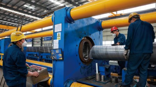
Cold drawing passes a steel tube or bar through one or multiple dies (sometimes over a mandrel), compressing and elongating it at ambient temperature. This process realigns grains and work-hardens the metal, enhancing tensile and yield strengths, while producing a smooth, scale-free surface with tight dimensional tolerances.
- Cold work strain (area reduction) typically ranges 10–50%; even moderate drawing can boost tensile yield by 17–27%
- Exceptional case: CK60 seamless tube drawn in two phases (15.1% + 13.7% reduction) achieved UTS = 1021 MPa, YS = 950 MPa, hardness ≈312 HV, elongation ~9%
Data: sciencedirect, eng-tips, wevolver.com.
Mechanical Impact: Strength, Hardness, Ductility
Analogy: Like forging dough into denser bread, cold drawing compacts structural elements.
- Tensile & yield strength: Improved by ~20–30% at 40–50% reductions.
- Hardness: Vickers hardness can rise to ~312 HV in CK60 tubes.
- Ductility: Elongation decreases—but precise thermal treatments (annealing) can restore ~9% elongation.
These figures highlight a power-packed performance—higher strength without sacrificing surface finish or stress capacity.
Process Stages & Critical Controls
- Die Sequence & Reduction Ratio
Multiple pass drawing with incremental die reductions (e.g., 15.1% → 13.7%) ensures uniform deformation and prevents cracking. - Lubrication & Friction Management
Use of phosphate or oil-based lubes minimizes friction, surface defects, and die wear. - Annealing Interim
Post-group drawing annealing reduces residual stress and refines grain structure—essential for maintaining ductility and dimensional stability. - Crack Prevention
Annealing before cold drawing reduces hardness (e.g., to HB250) and inter-lamellar spacing in pearlite, minimizing cracking risks.
Why Choose Cold Drawing vs. Other Processes?
| Feature | Cold Drawing | Cold Rolling / Hot Rolling |
|---|---|---|
| Temperature | Room temperature | Rolling: room temp; hot rolling: >925 °C |
| Tolerance Accuracy | Very tight (≈±0.01 mm) | Cold rolled moderate; hot rolled loose |
| Surface Quality | Bright, polished | Cold rolled smooth; hot rolled rough |
| Strength Improvement | +20–30% uplift | UP to ~20% for cold rolling; minimal in hot |
| Ductility | Reduced, recoverable via annealing | Moderate for cold; high for hot |
| Production Cost | Higher (dies, lubrication, multiple passes) | Lower, faster (especially hot rolling) |
Reference Blog: What is Cold Drawing and How Does It Compare to Hot Drawing?
Pressure & Load Calculations for Cold-Drawn Tubing
Engineers often need to calculate allowable internal pressure based on tube specs. Typical formula:
P=2σ⋅tD⋅SP = \frac{2σ \cdot t}{D \cdot S}P=D⋅S2σ⋅t
- σσσ: tensile strength of material (~410 MPa for steel)
- ttt: wall thickness
- DDD: outer diameter
- SSS: safety factor (4–8)
Example: With D=10 mmD=10 mmD=10 mm, t=3 mmt=3 mmt=3 mm, σ=410 MPaσ=410 MPaσ=410 MPa, S=4S=4S=4 → P≈39.4 MPaP≈39.4 MPaP≈39.4 MPa .
Influencing Factors & Microstructural Insight
Cold drawing compresses grains, producing strain hardening and directional texture. Metallography shows ferrite–pearlite uniformity in CK60 tubes post-drawing. Excessive drawing beyond 50% introduces high residual stress and low ductility—necessitating controlled annealing.
Reference Data & External Readings
- Yield strength boost: 17–27%
- CK60 seamless tube: UTS=1021 MPa, YS=950 MPa, HV~312, EL=9%
- Drawing force data (wire): ~163 kN at 47% reduction
- Cracking prevention via annealing: data on hardness and elongation vs. hydrogen embrittlement
Conclusion
Cold drawing remains the go-to process when steel components require precision, polished surfaces, and hardened strength—typical in hydraulic lines, aerospace tubes, and high-pressure structural frames. With documented strength increases of 20–30%, tight ±0.01 mm tolerances, and reliable pressure performance, it outpaces both hot and cold rolling. Yet it’s a nuanced process demanding multi-pass controls, lubricants, and stress-relief annealing. For engineers, grasping these technical details is key to designing optimized, durable tubing systems.
Let me know if you’d like performance charts, FEM simulation insights, or heat-treatment cycle recommendations to augment this article!

